Busbar Installation in a Live Indoor Substation
Project Overview
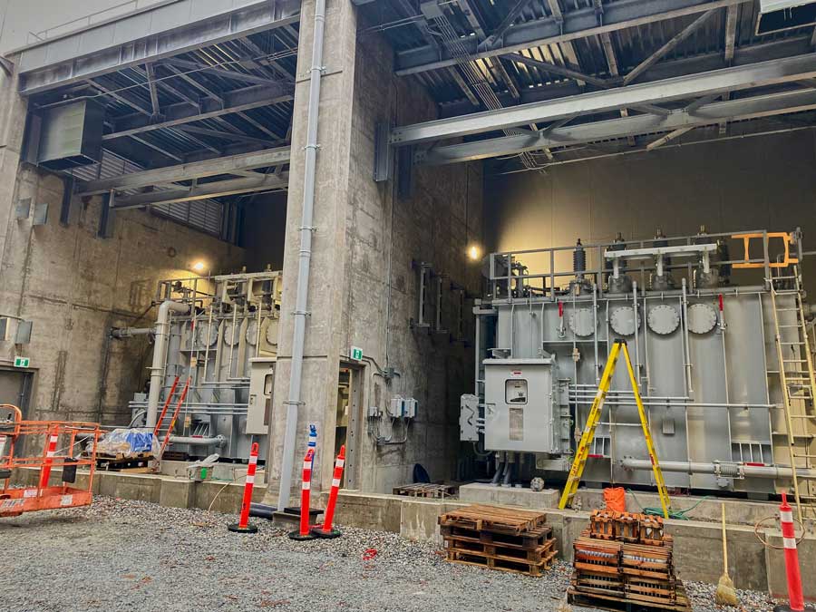
A major utility company faced the challenge of upgrading the electrical bus system in one of its critical indoor substations without shutting down the entire facility. The goal was to install over 300 meters of Duresca fully insulated 36,000 Volt busbar into the substation while keeping key parts of the substation live, ensuring continuous power delivery to critical infrastructure and minimizing disruptions to the local power grid.
The project required precise coordination, advanced safety planning, and the use of specialized equipment to ensure the successful and safe installation of the busbar system in a live high-voltage environment.
Key Challenges
Working in a Live Environment
The substation needed to remain energized during the installation due to its critical role in the electrical grid. This posed significant risks to the installation team, requiring extensive safety measures to protect both personnel and equipment.
Complex Indoor Layout
The indoor substation had limited space, making the maneuvering and installation of the busbar system challenging. The team had to carefully plan the routing of the busbars, ensuring they maintained safe clearances from energized components.
Tight Deadlines
The utility company had a strict deadline for completing the project due to operational constraints. This necessitated the installation work to be completed on time without compromising safety or quality.
Project Planning and Preparation
Installation Process
Post-Installation Testing and Commissioning
Once the entire 1000 meters of busbar were installed, a series of rigorous tests were conducted:
- Insulation Resistance Testing
All sections were tested using a megger to verify the integrity of the insulation system. - Thermal Imaging
A thermal camera was used to scan the connections and busbar sections for any hotspots or areas of concern, ensuring that all connections were properly made, and no parts were overheating. - High-Potential Testing
The system underwent high-potential testing to confirm the dielectric strength of the insulation under operational voltages.
The installation passed all tests, with no issues detected in either the insulation or electrical continuity of the system.
Outcome and Benefits
The project was completed on time and within budget, meeting the utility company’s strict deadline. The 1000 meters of insulated busbar were successfully installed without any incidents, and the live substation continued to operate without interruptions.
Minimal Disruption
By keeping the substation live during the installation, the utility company avoided power outages and maintained the reliability of the local grid.
Increased Safety
The insulated busbars significantly enhanced the safety of the substation by providing a robust, long-term solution that reduces the risk of electrical faults and minimizes phase-to-phase clearances.
Optimized Space Utilization
The compact design of the busbar system allowed for better use of space within the indoor substation, enabling the addition of future equipment without requiring a full redesign.
Lessons Learned
Careful Planning and Coordination
Successful installation in a live substation requires precise planning and coordination between the engineering, safety, and operations teams.
Safety First
Working in a live environment presents significant risks, but with the right safety protocols and training, these risks can be mitigated. Regular risk assessments and the use of insulated tools and barriers are essential.
Time Management
Dividing the installation into smaller, manageable sections and performing rigorous testing after each section helped keep the project on schedule and ensured that each part was installed safely and correctly.
Conclusion
The successful installation of over 1000 meters of insulated busbars in a live indoor substation demonstrated the feasibility of upgrading critical electrical infrastructure without compromising system reliability. Through careful planning, the use of advanced safety measures, and strong collaboration between teams, the project was delivered safely and efficiently.
The project not only increased the operational capacity of the substation, but also enhanced its safety and resilience for the future.
Interested in learning more about how Sasco supports data centre builds in BC? Contact us to discuss your project.


